


MK3s-z-axis-top-spacer.step
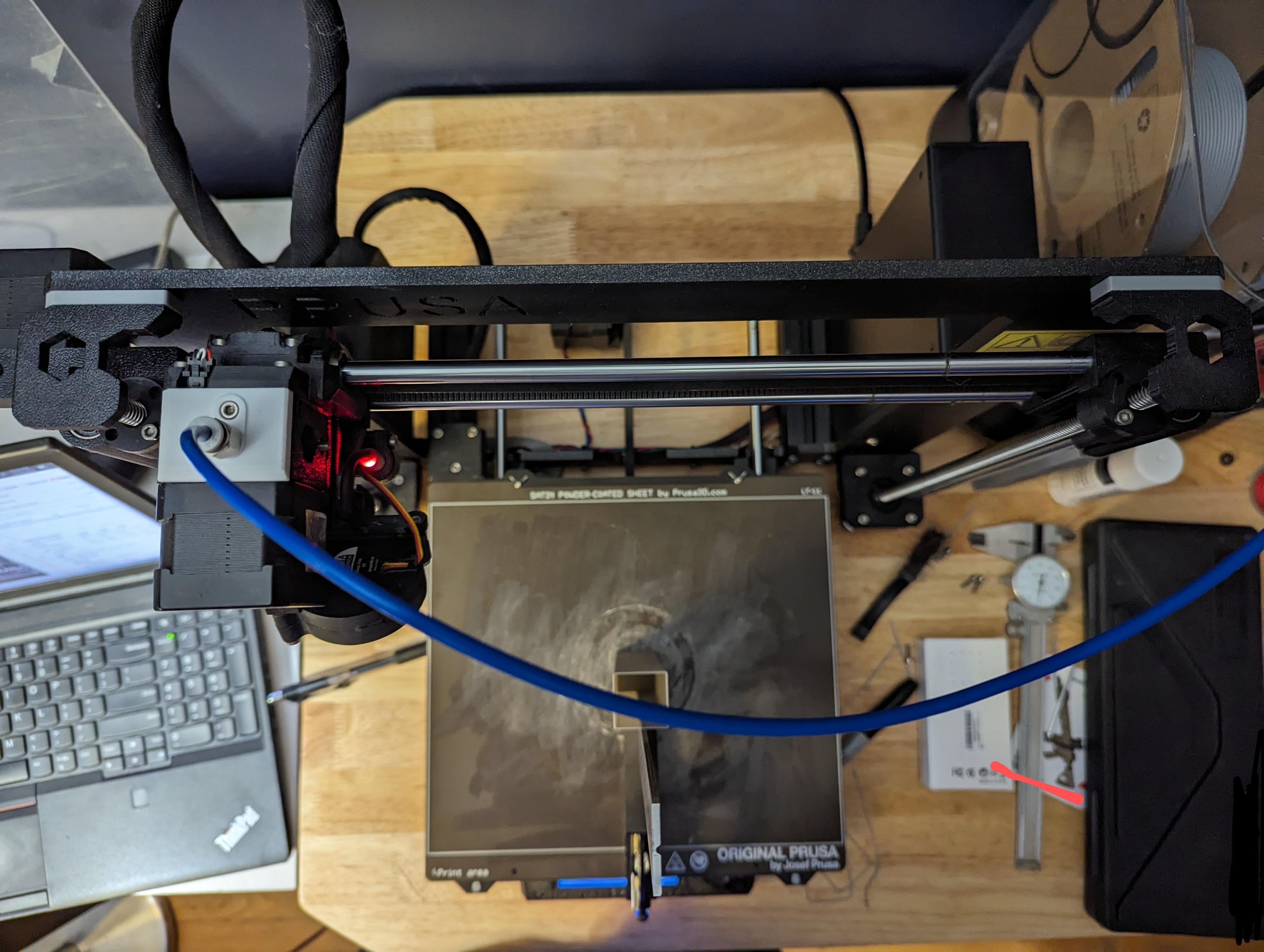
If your Z axis is out of square in the Y-Z plane (leaning towards the back) then this spacer might be useful for you. I just extruded it from the profile of the top bracket released by the manufacturer.
You can calculate the thickness with a simple linear relation. Print a tall rectangle, place a square against the base and use a caliper depth gauge or whatever to measure the deflection at the height of the measurement from the build plate. Then using the length of the linear rod (~12.25") you can get a spacer thickness in inches with (deflection / measurement height) = (spacer thickness / linear rod length). Or use a protractor and trig like a fancy person.
Make sure to use longer fasteners and not strip the threads in the frame. I had some M3x12s that worked well but slightly longer would be better.
One degree off might not seem like much but my parts couldnt be assembled as a result!
MK3s-z-axis-top-spacer.step

Wolf - Cinder Hatchling

River Otter - Cinder Hatchling
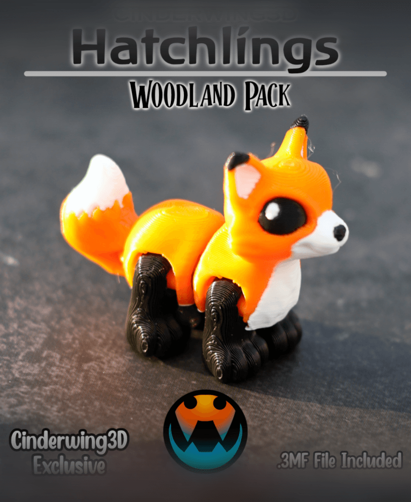
Fox - Cinder Hatchling

Flappy Head Dino - Hatchling

Snappy Water Dino - Hatchling

Racoon - Cinder Hatchling

PlayBook'd - Chess

Ducky Dino - Hatchling
![Tiny Mushroom Dragon/Wyvern and Mushroom Shelf [Gazzaladra Collab] 3d model](/_next/image?url=https%3A%2F%2Fstorage.googleapis.com%2Fproduction-thangs-public%2Fuploads%2Fenhanced_images%2Fv1%2F41421592-2019-4923-abae-c3e83a110400%2F0_2.jpg&w=3840&q=75)
Tiny Mushroom Dragon/Wyvern and Mushroom Shelf [Gazzaladra Collab]

The Rail - Tripod Attachment

Turkey - Cinder Hatchlin

Henriegga – The Chocolate Egg-Laying Chicken

Moose - Cinder Hatchling
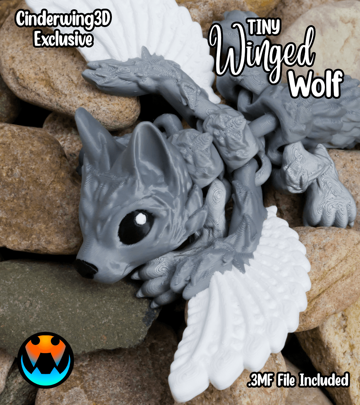
Tiny Winged Wolf
.png&w=3840&q=75)
PlayBook'd - Four in a Row
.gif&w=3840&q=75)
Candy Creeper Pug - Candy Dispenser

Window Pikachu - Pokemon

Charmander Window - Promo Card - Pokemon

PlayBook'd - Sea Battle