


Horizontal Spool Holder 608
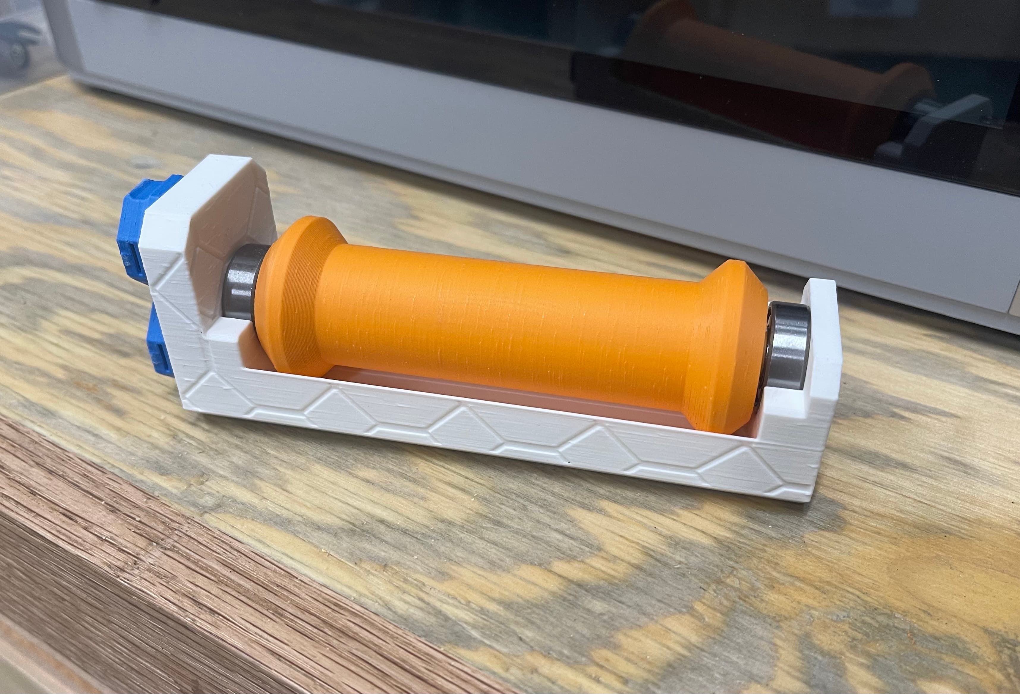
Yes, I need an AMS.Maybe 2. But I'm not finding the AMS Light at acceptable prices, and I still have shelf space, so let's go with another horizontal spool holder. I could just print another of the ones I shared earlier, but I recall mentioning that that could be remixed to use a 608 Skate Bearing, rather than the LM11959 bearing that one uses. Don't get me wrong, I like that bearing, and think it's one of the better bearings for this solution, but it's probably not something makers have rattling around in their spare parts drawer. Roller Skate bearings? That's a different matter. They also cost quite a bit less. For a project that I've abandoned I picked up a bundle of 100 ea, 608 bearings, in plastic sleves for under $20. Just checked, and that bundle with the bearing I've pictured, a 608-2RS 100 count is available on Amazon for $17.79, or at least that's the price I would pay if I didn't have a couple hundred around here already. The RS on that part number means that these have rubber shields. The use case we have here may not need that feature, as the spindle completely covers the bearing from above, and there isn't a lot of air flow under the bearing that would bring dust up into them, but I know some of us are using glass filled, and carbon filled filament, and the dust particles from those may be capable of doing significant damage to bearings. The metal shielded bearings that you often see are the 608-zz variety, and you can possibly save a buck on 100 count. And of course you can order any 608 variety bearing in counts of anything from 1, 2, 10, 20, 30, 50 or 100. (Or at least one of those counts.) There are also bearings where balls, or races are ceramic, If you are on YouTube, Clough42, James, has compared some bearings for some of his projects, and I'm sure others have as well.
My only complaint about the 608 bearing is that while it's sometimes called a thrust bearing, that's from the center of rotation outwards, rat her than thrust along the axis of rotation. We're using it for the latter here. Fortunately we're not going to be putting a lot of stress on that axis, the hardened bearing balls and races unlikely to explode from even a 5 kg axial load, but if you use one for this job, it may be a good idea to check on it every year or so for excessive wear, and/or replacement.
You may note that the spindle is in a bit of an odd shape here. The design of the spindle is such that it has a small lip at the outside edge of the spool to help retain the spool if it is loose on the spindle core. The spindle core is set up to handle spindles with at least a 50 mm hole through the axis, and many of the spools I've got have several mm of additional space there. These spools are also 200 mm diameter, and the lip goes out to 210 mm in diameter. If I just printed this on an Ender 3 series, or a Bambu P1 or X1 printer, I could print an entire disk on one of those printers. But perhaps you're using an A1 Mini, as I did for this print? The size of that bed is about 180mmx180mm. A 210 mm diameter model isn't going to fit on that. So I designed it starting with the full circle, then fit it into a 175x175 printer space. No it's not going to fit on the 6"x6" PrinterBot Full Metal Solid printer, but that's OK. I'm not using that printer these days. It should print on any printer with a bed that's larger than 175mm squared with a print height equal too, or greater than 100 mm.
The print in the images was printed in High Speed PLA from Crality. Obviously not the spool that's in the image, but from the same purchase. PLA is a fine material for this, as it generally prints easily, and once printed I don't envision anyone using one of these to be leaving it in an environment where the plastic will be exposed to temperatures close to it's glass temp. That doesn't mean that it won't deform over time, I expect it will, just that it's going to be the same deformation you should expect any time you put PLA under pressure over time.
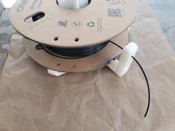
The base has a feature that I'm still working on. It has both a feed slot for filament to be fed through, and a hole near the top of the feed arm. The hol has a large fillet to help guide the filament through from the spool side, and a larger squared off hole on the exit side. If you want to add a reverse bowden tube fitting here to give the filament a clean path to he printer, this hole may need to be opened up a bit. For now it's a fairly small hole, if people have specific dimensions they would like to use for their particular fittings, I'm happy to post updated bases.
The through hole is 2.1 mm in diameter, which I've found gives me a free flow for the 1.75mm filament to go through. I was seeing a bit of resistance at 2.0. This may be hole expansion, but for the most part we're not printing in a direction where hole expansion should be noticable. On the other hand I print these with 0.28 mm layers, and there may be a bit of sag. That may be cleaned up with a small drill, but I decided to print a bunch of test parts, and this ended up being the size that worked for me. Your mileage may vary, and perhaps I've pointed you at some things to check in your slicer. I think there are test models out there that let you check to see how well tuned your printer is.
The fittings for the bearing are a fairly close tolerance as well. Close enough that the spinel hole for the bearing takes a bit of work to extract a bearing after it's inserted (It sits mostly flush with the bottom of the spindle in my case) however the 8mm core the center of the bearing rides on was a bit loose. I've added some tapered wings to that so that as the bearing is seated on the core, it gradually gets a tighter fit. This is not permanent though, so mostly just be aware of that. The design should leave clearance all around the parts in motion to prevent issues with interference, or even friction of parts passing too close. (Yes, technically that's interference as well.)
You may notice that one of the wings on the spindle spool guide center has a hole in it. I specifically designed the crossed guides so that as the filament is being drawn off the spool, you can see the spool turning, even without having to see the surface. of the spool. This hole is mostly just an experiment to help keep track of full rotation speed for the filament. Remember that the same speed of draw off from the spool will result in faster rotation of the spool as the spool empties. If you see the hole coming by more rapidly, it may help you recognize that you will need to replace the filament soon. Or maybe not.
Feel free to let me know if you have a request for this, or any of my models.
Edit - I've updated the 'base' with a design that should allow filament to feed through the top hole. This is dependent upon how you put the spool on the spindle, as it's picking up the loose end, rather than wrapping around the arm. The design also has better spacing for a ptfe reverse bowden tube though this may require a remix if you want to fit a ptfe hose fitting to get it to fit threads properly. This is currently an attachment, as I'm not seeing a way to add it to the primary model and parts collection.
Horizontal Spool Holder 608

Horizontal Spool Holder using BBs as rollers.

Horizontal Rewind Spool Holder
Multiboard Filament Spool Roller

Horizontal filament guide for Bambu labs printer

Spool Plug: Horizontal Filament Spool Holder

Wire shelf hanging spool holder for Filler spool holder
Horizontal Spool Holder on Smooth Bearings

2020 Spool Holder Horizontal Position

Large horizontal filament spool holder (v-core 4 leftover bearings used)

Adjustable Spool Holder - FLSUN QQ (608 zz bearings)

Roller filament spool holder for mk3 608 bearing

#TidyDesk Headphone and phone holder. Horizontal phone holder iteration 4, original 16

#TidyDesk Headphone and phone holder. Horizontal phone holder iteration 3, original 15

#TidyDesk Headphone and phone holder. Horizontal phone holder iteration 2, original 18

Bambulab A1 Spool Holder Holder

Gridfinity Spool Holder with Spools

Threaded spool for Wire Spool Holder

#TidyDesk Headphone and phone holder. Vertical and horizontal phone holder 3 original 19

Auto-Rewind Spool Holder for Spannerhands Spool System (MM)
