

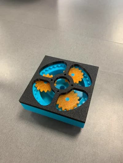
Planetary Gear Benchmark and Demo
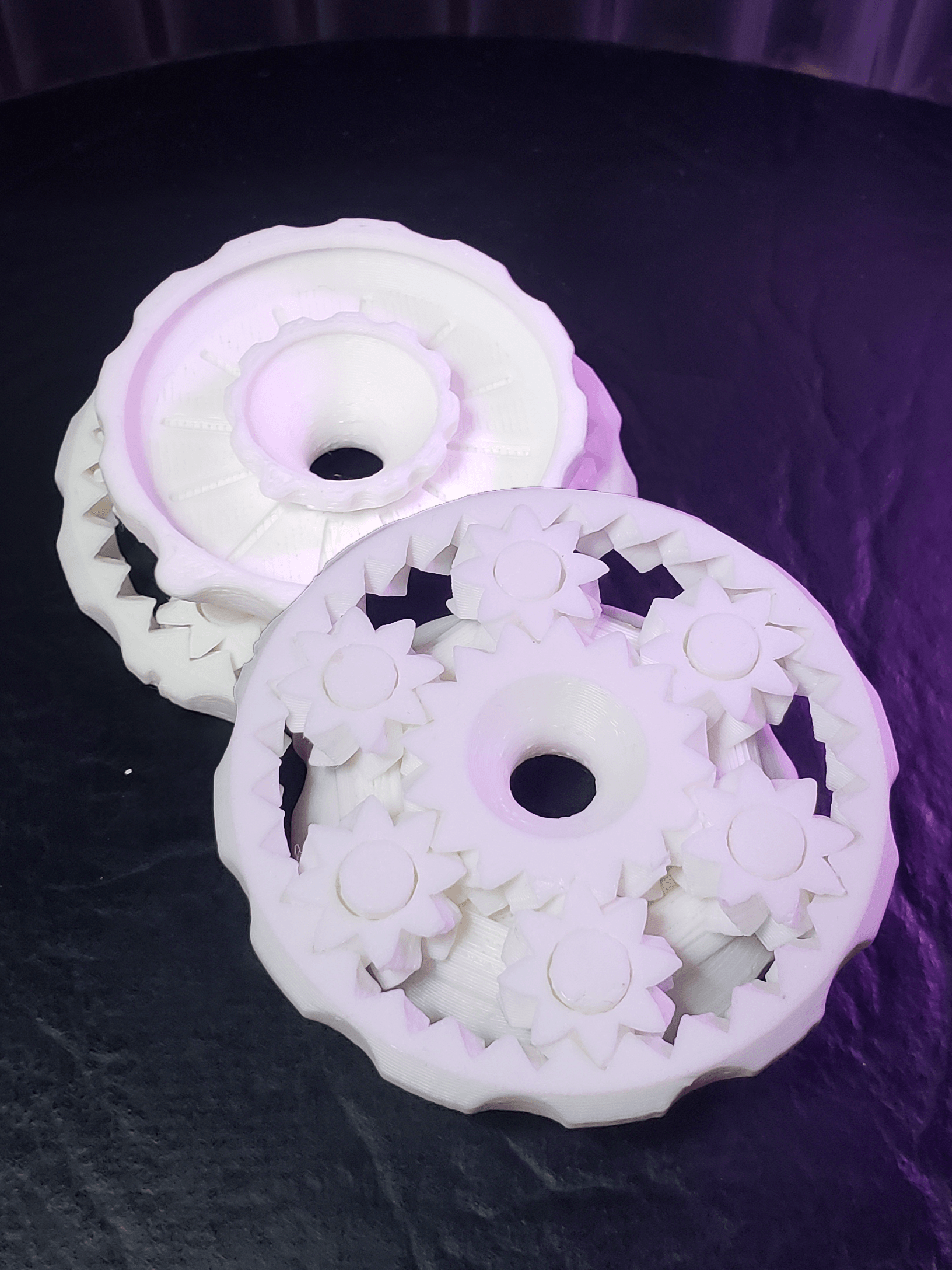
This is both a demo of planetary gears and a benchmark to verify that you can successfully print my other designs. It has a system of planetary gears connected to 3 rings, each with various markings to help you understand how planetary gears work.
🎉 Prints pre-assembled and without supports! 🙌 It's print-in-place, meaning it should work right off the buildplate! It is carefully designed with 3D printing in mind, so there shouldn't be any issues with tolerances, overhangs, or first-layer squishing.
If you can print this, you can print these other models!
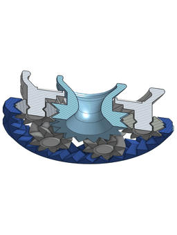
How It Works The bottom layer (closest to the gears) acts as the ring gear. The outer top layer is connected to the carrier, which is attached to the planets with a rotating joint. Finally, the center top layer is connected to the sun gear in the center. By holding and turning different combinations of rings, you can get 6 different gear ratios. By playing with the demo, it becomes easier to understand how planetary gears work.
Basic Print Settings
- 0.2mm layer height (or 0.1mm, but other heights may not slice correctly)
- 100% infill
- No supports
- No raft/brim
- Designed for 0.4mm nozzles (but should work fine with smaller ones)
Advanced Slicer Tweaks
- Some slicers may require setting the top and bottom layer heights to 0, to avoid weak geometry on thin tapered parts like the carrier posts.
- I had to do this for S3Dv4.
- Requires bridging, which may need to be turned on in your slicer.
- If it still doesn't bridge, make sure there is at least 1 bottom layer in your slicer.
- S3Dv4 also requires at least 1 bottom layer for bridging to occur.
- Make sure your "Minimum Extrusion Length" is set to something small, like your nozzle width.
- The defaults in S3D incorrectly prints the small gears as hollow.
Post-Printing Instructions When removing the part from the buildplate, be careful not to put excess prying stress in the planet gears (the smallest ones). Doing so can rip off the post caps holding them to the carrier. Instead, let your bed cool to the proper temperature for removal, then carefully scrape all pieces from the buildplate separately.
Do not use already freed parts of the print to apply force to still-adhered parts! Go slow and careful with a spatula and you'll get it!
Planetary Gear Explanation By holding the carrier still and turning the ring gear, you will see a 2:1 increase in speed on the sun gear, however in the opposite direction. Similarly, you can turn the sun gear to get a 1:2 reduction on the ring gear.
By holding the ring gear still and turning the carrier, you will see a 3:1 increase in speed on the sun gear, this time moving in the same direction. This is due to the 2:1 gear ratio between the ring and sun gears PLUS an additional rotation as the carrier (which was a still reference frame before) also makes a full rotation. You can also turn the sun gear to get a 1:3 reduction on the carrier.
Finally, by holding the sun gear still and turning the carrier, you will see a 3:2 increase in speed on the ring gear, which is also moving in the same direction. This is because the 1:2 ratio and the 3:1 ratio get combined due to the reference frames involved. You can turn the ring gear instead to get a 2:3 reduction on the carrier.
The ring gear has 32 teeth, the sun gear has 16 teeth, and the planet gears have 8 teeth. The base gear ratio of 2:1 comes from the ratio of the ring teeth to the sun teeth. The planet teeth are inconsequential for the gear ratio, but they DO need to be selected correctly for the sun and ring gear being used.
💖 Designed with FreeCAD! Thank you to the amazing FreeCAD community! 💖
Planetary Gear Benchmark and Demo
SpikeRoll Micro - Tactile Spinning Layered Fidget Toy
SpikeRoll Mini - Tactile Spinning Layered Fidget Toy

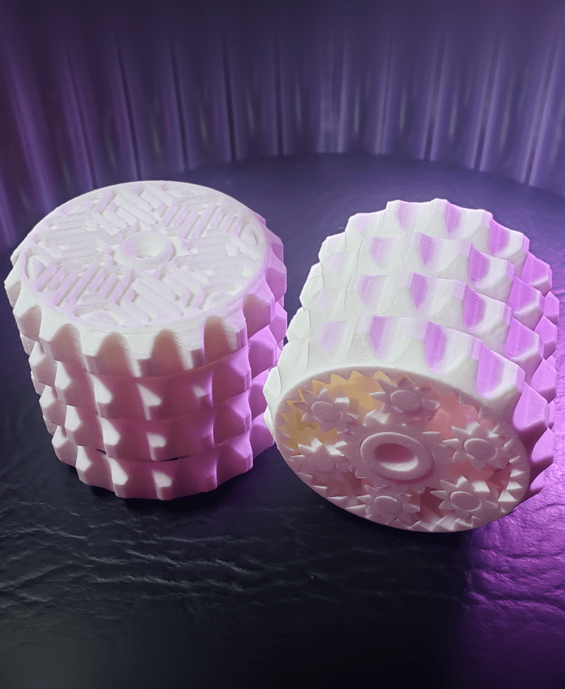
SpikeRoll - Tactile Spinning Layered Fidget Toy

OrbitStack - Tactile Planetary Gear Spinning Layered Fidget Stim Toy

OrbitStack Knob - Tactile Planetary Gear Spinning Layered Fidget Stim Toy
OrbitStack XL - Tactile Planetary Gear Spinning Layered Fidget Stim Toy

Paper Creasing Tools (Pick, MiniPick, Domino)

Cthulhu Statuette (with Mysterious Writings Added)

Ball-Socket Swivel Rope Hanger (Ceiling Fan VR Cable Management)
Infest The Rats' Nest Skull (Official KGatLW 3D Model)

Nintendo Switch Game Card / Cartridge RCM Jig

Planetary Gear Print-in-Place Demo

Mini Planetary Gear Print-in-Place Demo

Planetary Gear Mechanism | Functional 3D Printable Gear Assembly

The Impossible Planetary Gear Fidget

Gearfinity Planetary Gear Stage

Planetary Gear Cube Fidget Toy by Ruven Bals

Compound Planetary Gears 1300:1
Planetary Gear Box
