


Hextraction: Sloping underboard tray
A tray to put underneath your Hextraction board, shaped such that sunk balls will roll to the catch areas in the front.
THIS VERSION IS FOR THE "FANCY" VERSION OF THE BOARD. The basic version of the board has its feet in a different position, and I don't yet have the proper coordinates for those. IF YOU HAVE A BASIC BOARD, SOME SPARE FILAMENT, AND A WILLINGNESS TO HELP, PLEASE CONTACT ME. It should not be too onerous to get it right.
Screw holes below the support pads allow the back supports to optionally be screwed in place; however, this is usually not necessary as the support pads are shaped to hold the supports in place using the standard leveling screws and gravity only.
Designed in FreeCAD 0.21; the FreeCAD master file is included. Most dimensions are parameterized in the sketches "XYGeometry" and "YZGeometry".
The standard version is 300×280 mm; the smaller version is 280×270 mm. The only difference is in the geometry parameters.
Hextraction: Sloping underboard tray

Segmented tray with sloped edges (many configurations 2x2, 4x4, etc)
AOS Unit Trays / Bases - Muddy Rubble Slope
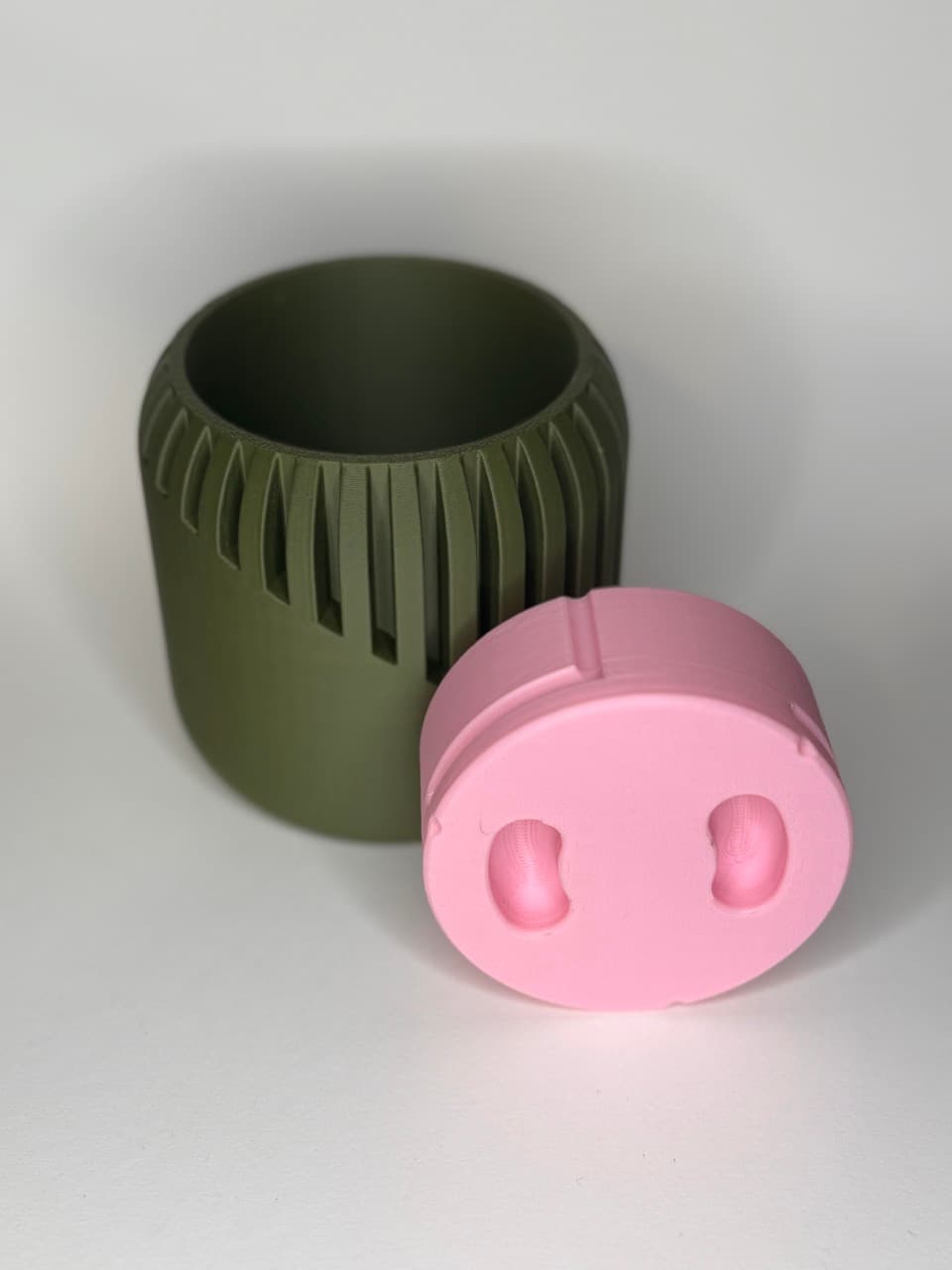
Slope Planter with Hidden "Pig Nose" Drip Tray

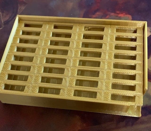
Spool Drawer Divider V2

Sink Tray Type 1

SPONGE TRAY
![[Hextraction] Basic Tile Prints in Vase Mode 3d model](/_next/image?url=https%3A%2F%2Fstorage.googleapis.com%2Fproduction-thangs-public%2Fuploads%2Fattachments%2F6f37c90e-baaa-411f-acc9-9eadb3354dd6%2Fphoto_2023-07-06_13-41-10.jpg&w=3840&q=75)
[Hextraction] Basic Tile Prints in Vase Mode
![[Hextraction] Y tile prints in Vase Mode 3d model](/_next/image?url=https%3A%2F%2Fstorage.googleapis.com%2Fproduction-thangs-public%2Fuploads%2Fattachments%2F484b3e78-7a30-438f-adb1-a13c2a0051a5%2Fphoto_2023-07-07_11-45-09.jpg&w=3840&q=75)
[Hextraction] Y tile prints in Vase Mode

Compact Gourde Drainer
![[Hextraction] C tile prints in Vase Mode 3d model](/_next/image?url=https%3A%2F%2Fstorage.googleapis.com%2Fproduction-thangs-public%2Fuploads%2Fattachments%2Fdc640362-da9b-4ad5-9302-c53e7485c16a%2Fphoto_2023-07-07_11-40-20.jpg&w=3840&q=75)
[Hextraction] C tile prints in Vase Mode

ECO DRAIN | CUTLERY DRAINER
Soap/Sponge Tray

Ripple Soap Tray

Pipe Planter (Mario Themed) With Drip Tray (2 Versions)

Hextraction - Shrink Ray Tile Improved

Soap Holder Type 3

Organic Planter - For Succulents, Cacti, Other Small Plants

Criss Cross Dice Tower with dice tray - one piece - no supports
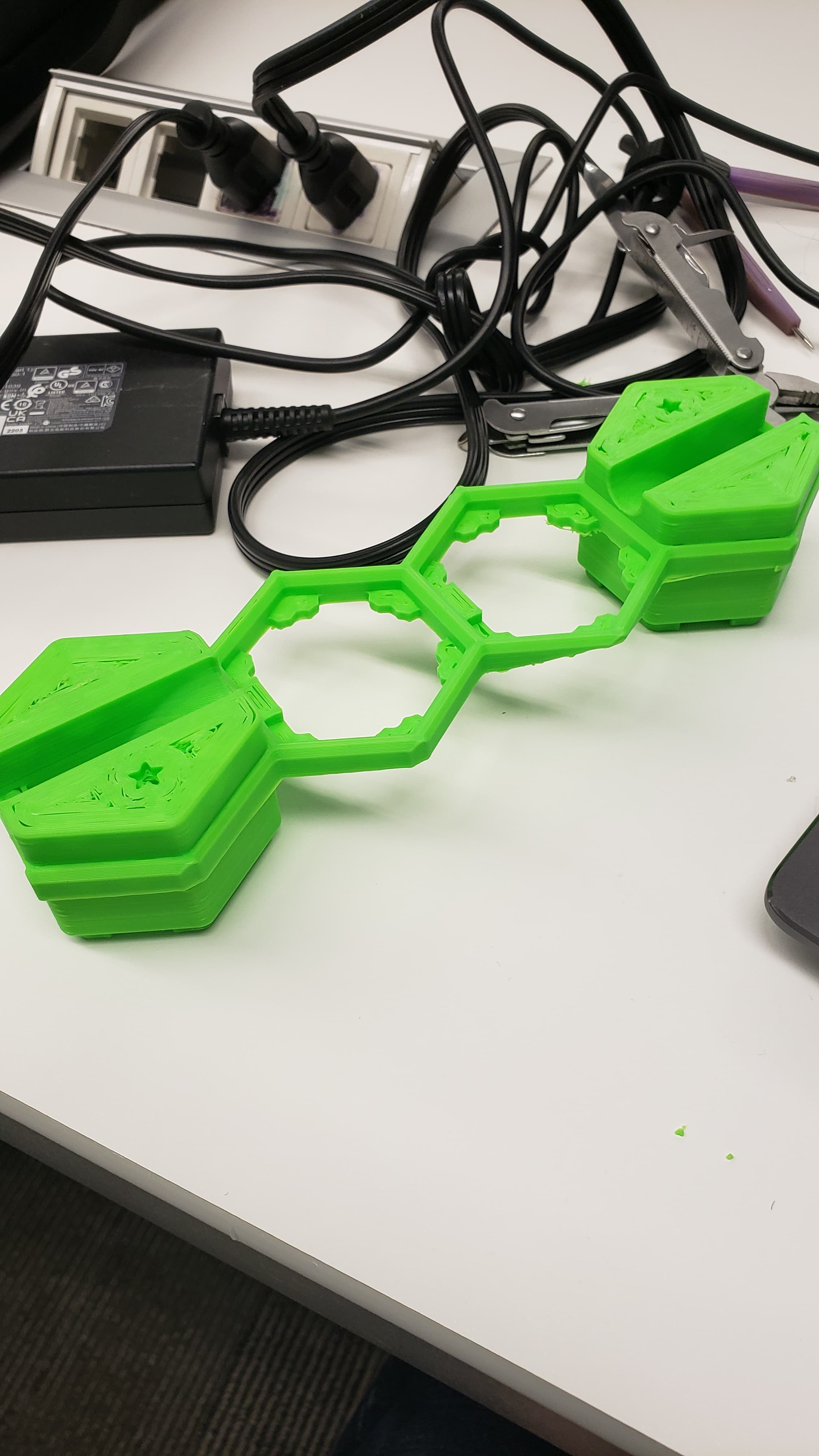
Multitile Bridge V1

Heads up: I only realized after I printed almost 400 grams worth of filament that this is not compatible with the basic version of the board. The fancy version has feet placed farther forward so the feed on my don’t fit. I don't blame the OP, I should have paid closer attention.
Checking in?
Ok I think I understand I get what you need. I'll pass you those measurements this weekend hopefully. I don't need the master files, I can just measure the points you need on the official step file for the basic board.
When I developed the board, I printed a thin slice of the tray (I called it a "giraffe" because of the shape) to tweak the alignment until I got a good fit.) I can get you such test models if you give you the dimensions, or, if you have FreeCAD, I can send you the master file to generate them.
To be specific, the distance that matters is from the point where the goal tray goes from angled to horizontal – in other words, where it touches the ground – to the center of the support foot/adjustment screw. I assume the foot/screw is the same (as far as I have been able to determine, it is.)
The best origin to measure from is the point where the goal trays go from angled to horizontal.
The legs on the basic board are the same width apart on the fancy board, so the holes on the tray only need to slide back some. What measurement are you looking for exactly so I can provide you the spacing? Like spacing relative to what vertex of what part, something like that
Yikes. I didn't realize that (I have the fancy version of the board.) I added a warning to the description.
I guess I need to find out the geometry of the feet for the basic board and put them into the XYGeometry, unless you have figured them out by now?
Dam it barely doesn't fit on my printer.
Anyway, it took less than 5 minutes to make the smaller version so not exactly a big effort :)
Another thing: on my printer (Sovol SV04), even though the plate is square, I ended up having to print (the large version) such that the larger dimension is along the Y axis (rotated 90°). The reason seems to be that the slicer wants to reserve a strip on the left along the Y axis for starting up the nozzle, even though it has a waste bucket at its disposal.
The good part is that the surface area contact with the plate is absolutely enormous, so if you can get the first layer to print it would be highly unlikely to move.
Ooh thank you so much! Yeah I don't know why my slicer doesn't like when it completely covers the printing bed, but the smaller one has no such issue. Will try to print one once I receive my order of filament (though dam it's estimated 30h of print and 283g of filament I really hope I won't have adhesion problems).
That's odd; the tray is 280 × 300 mm in the standard version. I made a 270 × 280 mm version I'm going to upload in a minute.
It's a Creality CR-10 V2, bed is 300x300mm.
What is the size of your printer?
Never used FreeCAD so installed it and tried, but even after finding the MaxX thing in the geometry and finding how to edit it, it just keeps saying "recompute failed" no matter what value I put and it doesn't change the actual model.
Just make sure you only change dimensions shown in red, not the ones in blue or orange.
The design is parametric; you might be able to reduce the dimensions down to what you need by adjusting the XYGeometry and YZGeometry sketches using FreeCAD.