


MiniMoto Educational Drivetrain V1-Fixed
Print Instructions
Quality
Layer Height 0.16 mm
Initial Layer Height 0.20 mm
Line Width 0.40 mm
Walls
Wall Line Count 3
Outer Wall Speed 25 mm/s
Inner Wall Speed 35 mm/s
Top/Bottom
Top Layers 5
Bottom Layers 5
Infill
Infill Pattern Gyroid
Infill Density 40%
Temperatures
Nozzle Temperature 200°C
Build Plate Initial 60°C
Build Plate 55°C
Cooling
Initial Fan Speed 0%
Fan After Initial Layers 100% (or experiment with 80% if small parts curl)
Speed
Print Speed 85% of normal
(or reduce the Cura profile to match)
Outer Wall 25 mm/s
Inner Wall 35 mm/s
Travel
Z-Hop 0.3 mm
Avoid Printed Parts ON
Combing Within Infill
Disclaimer
Even with these settings, I cannot guarantee print quality as even something as small as dust on your build plate can lead to a spaghettified mess. To avoid this, participate in basic printer maintenance and use supports and brims (while supports and brims are not required, if you are new to 3d printing they can immensely reduce print failures.)
Before long prints:
- Clean the build plate with isopropyl alcohol.
- Avoid touching the build surface with your fingers.
- Inspect the nozzle for any plastic buildup.
- Remove any nozzle blob before starting or resuming a print.
_______________________________________________________________________________________________________________________
Assembly Instructions
Engine
- Insert a piston head into small side of a connecting rod (x4)
- Slide each piston assembly into a slot in the Engine Frame (Engine Frame should be upside down)
- Clip the crankshaft into the holes on the engine frame so that the piston slots are aligned with the pistons
- Clip the large engine of the connecting rods to the piston slots
Transmission
- Bend the 6 long arms of the Transmission Frame upward at the base (upward is the direction in which the holes open)
- Slide the smaller gear on to the back of the control shaft (The side where the transition gear is pressed on) with the 15-tooth side facing inward (toward the 15-tooth gear in the center of the shaft)
- Press the transition gear onto the back of the control shaft
- Slide the bigger gear onto the front of the control shaft with the 15-tooth side facing inward
- On one side of the Transmission Frame place the engine input shaft on the bottom slot on the front most arm (the arm that is closest to the middle arm)
- place the control shaft on the bottom slots on the middle and back arms
- place the power shaft on the top slots of all 3 arms
- close the frame (use glue or PLA welding to seal the adjacent arms together)
Differential
- insert one rear axle into the hole of the ring gear so that the bevel gear side is facing up (the side where the spider gear holders are)
- insert the spider gears
- pull down on the rear axle in the ring gear
- insert the spider gear at an angle so that one clip is in and one is not
- pull down on the clip in the holder and push outward (away from the rear axle) on the top of the spider gear
- repeat for the other side
Full Assembly
- insert the front axle into the two holes in the front of the Frame (the section of the Frame that looks like a U or n)
- insert the differential and free rear axle into the two holes in the back of the frame (the section of the frame that looks like an H)
- clip the back of the control shaft (the part with the bevel gear) into the hole on the crossbar on the Frame so that the bevel gear is flush with the crossbar
- insert the engine into the front of the frame using the 6 clips and the alignment shield (the alignment shield sits behind the axle)
Clip rims and tires to the axels if you want and enjoy!
MiniMoto Educational Drivetrain V1-Fixed

FCC Brillouin Zone (fixed)

IDPF, Index Distal Prosthesis, (Fixed)

Optical Illusion V1

MDPF, MIDDLE FINGER DISTAL PROSTESIS (fixed)

Wind-up Dual Planetary Gear

Ready to Assemble Toy Robot

Reuleaux Triangle Mechanism Kit Card

FPV "Model" Kit

Star Wars Legion Terrain - Imperial Endor Bunkers

Tensegrity of Creation of Adam
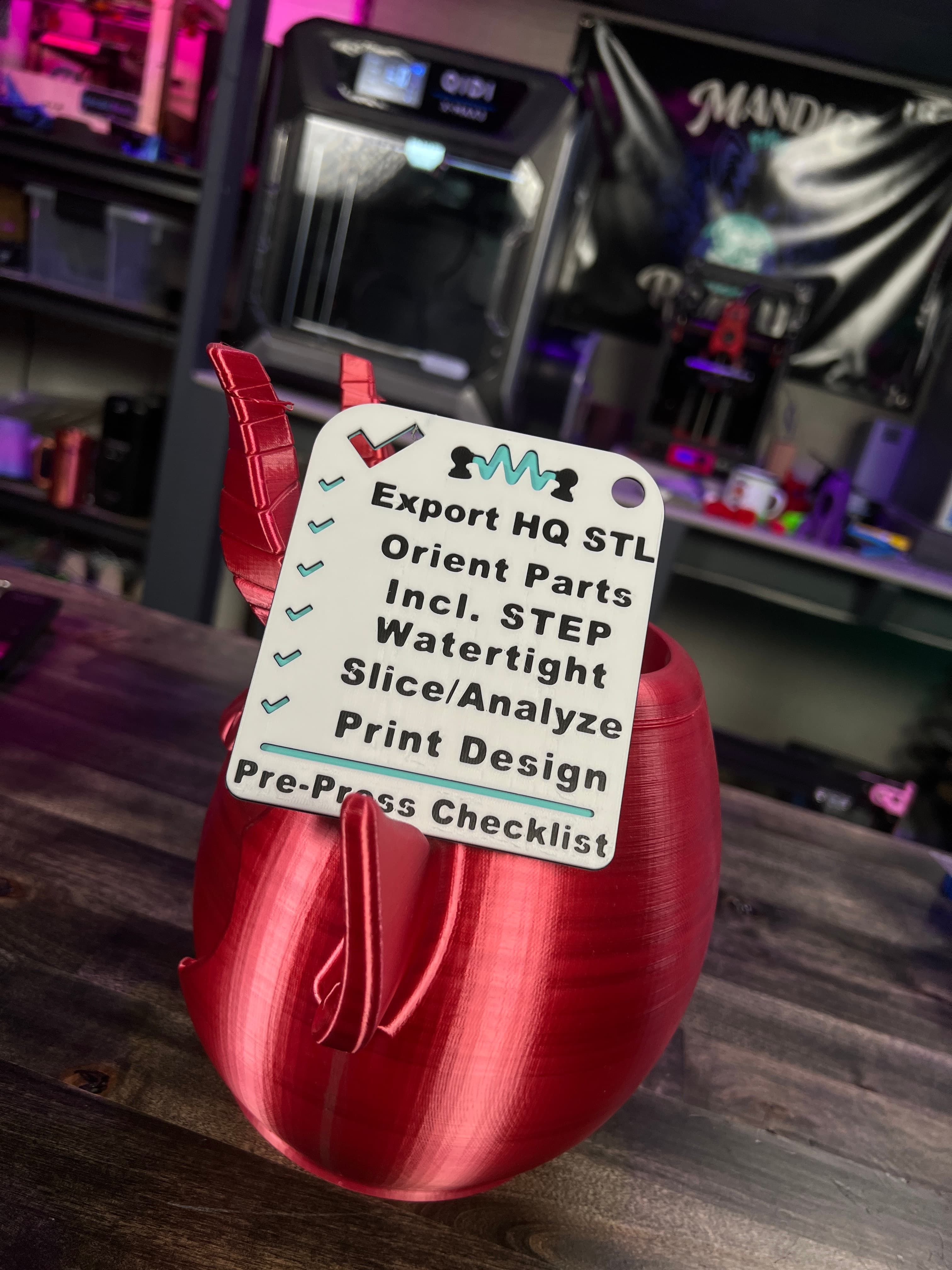
3D Design Checklist - Model like a PRO!
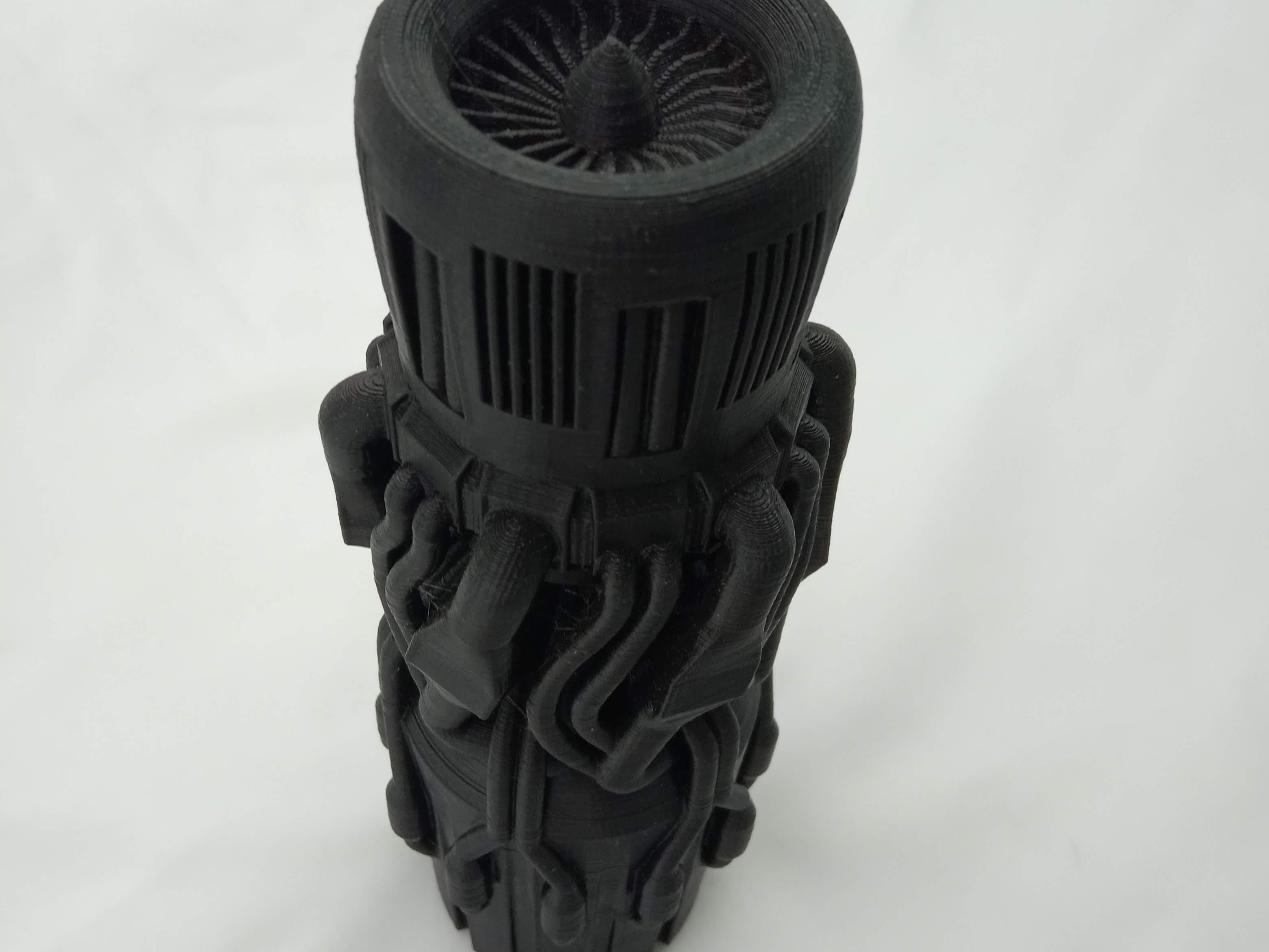
fusion 360 engine
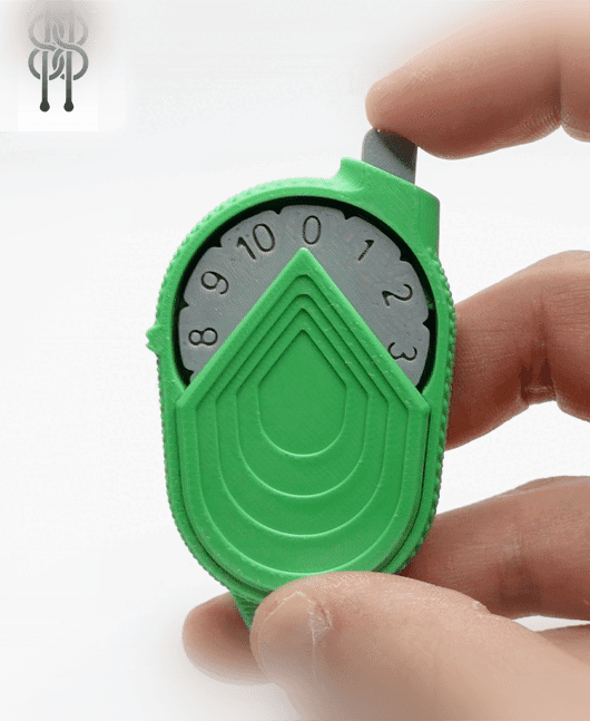
Mechanical Counter 0-10 - V1

c9kinetic Projector

Liquid Cat Fidget Toy Print in Place

Astrolabicon Pro // Ziggy
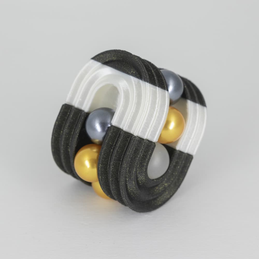
KWOB Puzzle // Ziggy A
Astrolabicon Pro

Icosahedron Earth // Folding Polyhedra
